Seawater Pro watermaker install on our Hunter 376 sailboat

By aaron.axvig, Mon, 03/09/2020 - 09:33
Watermaker system overview

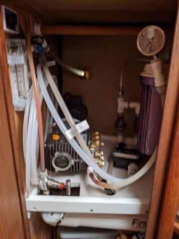
In this post I will document the Seawater Pro watermaker that we installed one year ago.  It currently makes 15 gallons per hour here in the Bahamas at about 850 PSI membrane pressure while consuming about 850 watts.

I ordered and installed the system in March 2019, probably total installed cost was about $3,100 and a solid week+ of learning, working and running to hardware stores.

  • $2,575 to Seawater Pro.  It looks like this $2395 item currently in their store is basically what I got.  I would really recommend getting the "remote control" version which is basically a pretty panel to put the controls and gauges in, but it is $400 more and you have to draw the line somewhere.
    • Base system price was $1,595
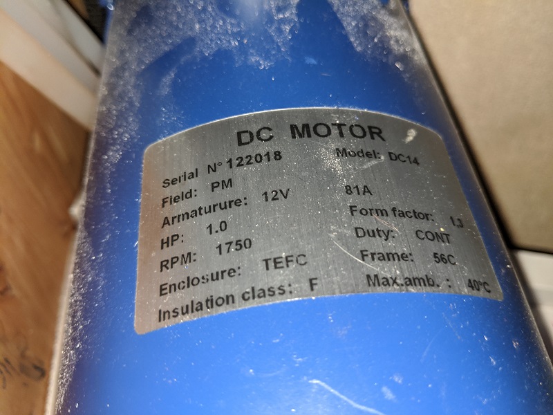
    • $699 for the DC motor and brass pump upgrade
    • $39 for the SW30-2540 membrane (an upgrade? I see they retail for more like $200 online?)
    • $80 shipping and some tax were the remainder
  • Additional costs rough estimates (one year ago by memory!)
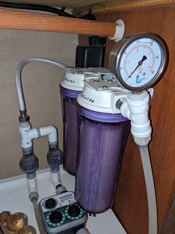
    • $250 for plumbing odds and ends not included "in the box"
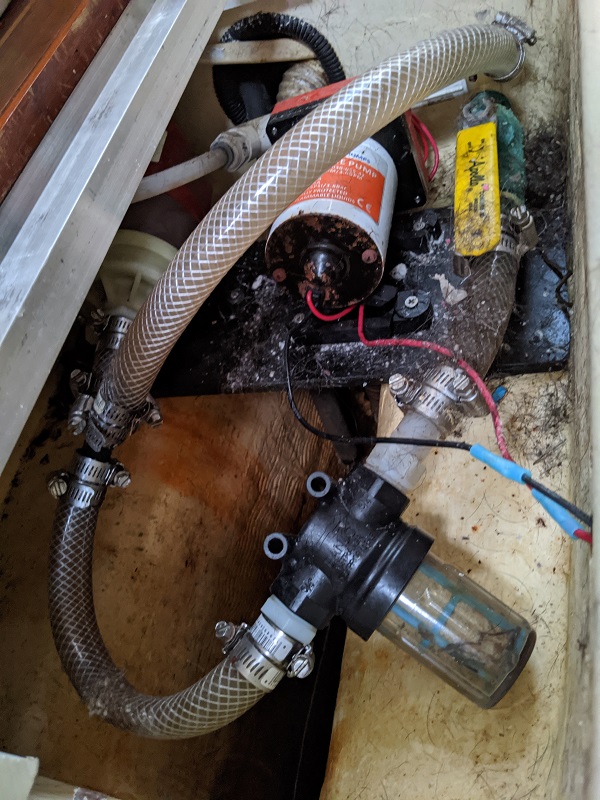
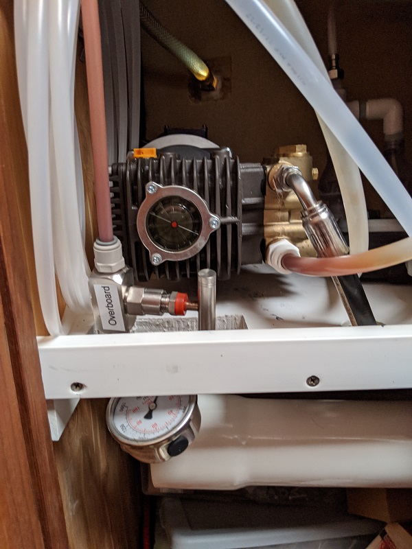
      • Boost pump is far from high pressure pump
      • Had to split air conditioner sea water intake (do not run AC and watermaker at the same time)
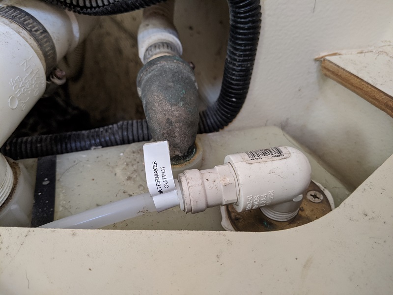
      • New dump overboard through the hull for salt water output
      • New input into top of water tank
      • Valves to direct product water overboard or into water tank
      • Misc. to get house water to the system for flushing
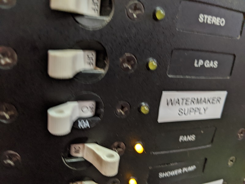
    • $250 for wiring
      • About 30 feet of 2AWG marine wire
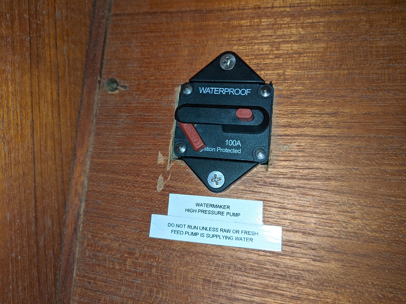
      • Circuit breakers
      • Compression lugs, heat shrink, looming, etc.

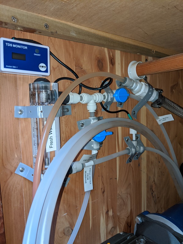
What the operating process looks like, plus notes about a few steps that we skip:

  1. Ensure needle valve is open (unrestricted).
  2. Ensure product water valves are set to flow overboard and put that dump hose out the v-berth hatch. (usually skip this and just dump straight into water tank...20 seconds of 2,000 TDS water is quickly diluted by the following hour or two of usually 100 TDS water)
  3. Turn on salt water boost pump.
  4. Verify that the pressure gauge before the salt water high pressure pump shows higher than 0 PSI (usually skip this, depends on cleanliness of sea water in the area).
  5. Turn on salt water high pressure pump.
  6. Tighten needle valve over about 20 seconds to bring pressure to 750-850 PSI, observing GPH meter rise to 15 GPH (or more, or less).
  7. Turn on the TDS monitor and observe it drop from around 2,000 to under 200.
  8. Open product water valve to water tank, and then close the one that dumps overboard. (usually skip this)
  9. Put away overboard dump hose. (usually we don't dump any water so skip this)
  10. Run for a long time, typically one to two hours.  Monitor both low pressure and high pressure gauges every 20-30 minutes, and also listen to the sounds of the system for interesting changes.
  11. Loosen the needle valve slowly over 20 seconds to bring high pressure to 0 PSI.
  12. Turn off high pressure pump.
  13. Turn off boost pump.
  14. Flush system with fresh water. This ideally would mean doing something with the garden sprinkler timer but I haven't gotten that to work so I flip open a valve under the settee. (usually we skip this)

So basically we are doing two "naughty" things.  We don't dump the initial product water overboard, but the math on dilution is quite convincing to me that it doesn't really matter, the water tastes fine, and we are generally healthy.  And we don't flush with fresh water after running, but the system performance does not seem significantly degraded.  Perhaps we will need to replace the $200(?) membrane earlier than the 5-10 years that people normally get out of them.

Our system has a 12V high pressure motor.  At operating pressure this alone seems to draw about 800 watts (65A at 12V), with the boost pump drawing the other 50 watts.  For our 4x 100Ah 12V lithium iron phosphate (BattleBorn) battery bank this is no problem.  It may not work so well on smallish lead-acid battery banks, in which case using a generator and 120V AC pump would be wiser.  If we run the generator our battery charger can put out about 90A so it can charge the battery a little in addition to keeping up with the watermaker draw.  But mostly we get enough solar from our 1100 watts of panels to keep up with the fairly liberal demands of the two of us.

Boat water systems diagram
The complete water system diagram on our boat.  The watermaker is half of it!
New input into water tank
The new fixture that I added on top of the water tank for product water to drop in.
Boost pump breaker
The breaker for the salt water boost pump.  Turn this on first!
Seawater plumbing under the floorboards
Under the floorboards with dog hair!  The seacock has the yellow handle on it, which flows to the strainer on the left.  Above that, a Y-valve goes to both the 120V AC pump for the air conditioner (top) and the 12V pump which boosts seawater to the watermaker's high pressure pump.  The "Watermaker Supply" breaker on the boat's breaker panel turns this 12V pump on.  Someday when I need to pickle the system I will have to modify this plumbing to provide a way to suck the pickling solution into the system.
Breaker under nav station
This breaker is under the nav station, like exactly where it could be bumped by a knee.  I think the labels explain enough for this picture!
Pump nameplate
Here is the nameplate on the high pressure pump motor.
Main watermaker parts overview
This is an overview of all the main watermaker parts on a shelf that I built in the v-berth closet.  If the photo was oriented correctly, from left to right: TDS and GPH gauges, coiled up hose for dumping product water out the v-berth hatch, high pressure pump, needle valve (silver handle), high pressure gauge peeking out under the shelf, fresh water flush timer and one-way valves, and sea water filtration.  The glowing thing in the back is daylight coming in through the through hull.
Seawater filtration
Seawater filtration!  Seawater leaves the boost pump and travels under the couch around the table, under the v-berth sink, through the space where the water tank is, and finally comes in through the left one-way valve.  Fresh water for flushing leaves the house pressure pump (I installed the carbon filter that came with the system so that it filters all house water...to remove any chlorine which would damage the membrane) and travels under the v-berth sink, through the space where the water tank is, and finally comes in through the timer and right one-way valve.  Then ideally a 20 micron filter and 5 micron filter.  I believe Seawater Pro says that the actual sizes don't matter much.  I just run 20 micron filters in both.  In dirty water they plug up pretty fast (3-5 hours?) so I have been known to just run one out of frustration...lasts longer then.  Not optimal for system life I guess.  In the Bahamas we have run with both for maybe 30 hours now and they are still quite clean.  I guess I didn't need the 20 filters that I stashed under the bed!  When the pressure on this gauge drops to zero it means the boost pump isn't able to pump enough water through the filters because they are dirty, so soon your high pressure pump will start making upset noises as it draws in air or a vacuum.  Not good for that, should be avoided.
High pressure pump close-up
A closeup of the high pressure components.  The high pressure pump has to be oriented with the yellow fill cap/dipstick facing up.  The pump can be rotated to any 90-degree position on the motor so if you need to bolt the motor to the wall that is fine.  Mine is bolted to the shelf, which is built out of PVC boards from Lowe's/Home Depot.  The big high pressure line coming out of the pump runs to the far end of the membrane housing which is under the v-berth bed.  And then you can see the "near" end of the membrane enclosure in this photo.  It has two connections.  The first is high pressure to the gauge you see here, this is what we run at 750-850 PSI.  Then the needle valve which lets some water past but still holds the pressure high.  Then that pipe (which mysteriously became dirty after a few hours of running) goes overboard through the hull in the back of the cabinet.  My positioning of these things is not ideal and I can't quite tighten one of the connections enough and still have them fit it the "custom" hole I made in the shelf, so I get a very flow drip in this part of the high pressure system.  The second connection is the product water output.
Plumbing for directing product water
This is the plumbing for handling the product water.  First it hits the sensor for the TDS monitor and then goes to the GPH meter.  From there I can choose to direct the water to a hose that I can put overboard out the v-berth hatch, or send it to the water tank.  A Y-valve would be ideal for this but I couldn't find the appropriate one in-stock at the time.

That's it!

Tags